


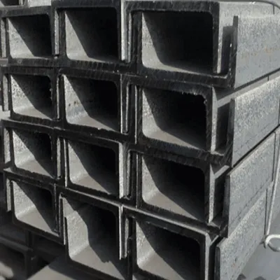


How a Demountable Barrier is Built Up
A rapidly deployed flood wall is a temporary structure assembled from three elements: vertical posts that carry the bending moment, horizontal panels or stoplogs that retain the water, and ground-level anchorage that transfers the load into a foundation. Vertical posts are commonly HEA or HEB sections or square hollow sections, chosen because a wide flange gives a stiff post with a convenient flat face for gasket contact. Panels are frequently rolled sheet pile sections or aluminium extrusions; where steel sheet piles are used, grade SY295 or SY390 to EN 10248-1 provides minimum yield strengths of 295 MPa and 390 MPa respectively.
The design load case is not the peak flood level alone but the combination of hydrostatic pressure, debris impact, wave splash and, in prolonged events, seepage under the foundation. Barrier height and post spacing are therefore set together: doubling the clear span between posts increases the bending moment in each post by roughly a factor of four for the same retained head.
Section and Material Selection
| Component | Typical section | Material | Governing standard |
|---|---|---|---|
| Vertical post | HEA or HEB 100 to HEB 200 | S235JR to S355JR | EN 10025-2 |
| Stoplogs or panels | Rolled sheet pile profile, 4-8 mm | SY295, SY390 | EN 10248-1 |
| Base plate and anchorage | Plate 10-25 mm | S275JR, S355JR | EN 10025-2 |
| Sealing gasket | Solid or inflatable elastomer | EPDM or silicone | Product specific |
| Corrosion protection | Batch galvanized | Zinc coating | ISO 1461 |
Galvanizing to ISO 1461 is the default protection for steel barrier components because the coating is abrasion resistant, requires no curing time and can be handled immediately after delivery, which matters for equipment that may be deployed within hours of being moved. Where the barrier sits in brackish or saline water, a duplex system adds a paint layer over the zinc to slow coating consumption.
Sealing, Anchorage and Foundation Interface
Watertightness is achieved at three interfaces: between adjacent panels, between the panel and the post flange, and between the lowest panel and the ground. Compression gaskets in a rebate or tongue-and-groove arrangement are the most common solution for the first two, while the base seal relies on a compressible profile clamped against a prepared concrete sill or on a flexible apron anchored upstream of the post line.
Anchorage design should account for uplift as well as overturning, because a partially flooded barrier creates a buoyant load on any hollow section. Cast-in sockets, chemical anchors into an existing sill and bolted base plates are all used; the choice is usually dictated by whether the foundation already exists. Anchor spacing and embedment should be specified from the overturning moment of the tallest configuration, not from the most common one.
Deployment Planning and Maintenance
A barrier that cannot be erected quickly has little value in an emergency, so deployment is a logistics problem as much as an engineering one. Practical measures include pre-installed ground sockets with removable covers, colour or number marking of every panel so that assembly order is unambiguous, dedicated lifting points, and a written erection sequence with target times per metre of wall. The PAS 1188 series provides a framework for specifying, testing and classifying flood protection products, including the design, performance and testing information a purchaser should require from a supplier.
Maintenance is mostly about the sealing system and the coating. Gaskets should be inspected before each flood season, stored flat and out of sunlight, and replaced when compression set is visible. Galvanized surfaces are inspected for white rust and for mechanical damage; small damaged areas are repaired with a zinc-rich coating. Anchorage bolts benefit from a light coating of corrosion-inhibiting grease and from a torque check at the same interval.
Frequently Asked Questions
Q: What post spacing is realistic for a demountable steel barrier?
A: Spacing is a function of retained water depth and post section, not a fixed number. A 1 m head with HEB 140 posts at 2 m centres is a common arrangement, while a 3 m head usually requires heavier posts and shorter spans or additional bracing. The governing check is bending and deflection of the post, plus the local capacity of the foundation.
Q: Can the barrier be deployed on an existing concrete kerb?
A: Yes, provided the kerb can resist the overturning moment and the anchor pull-out load, and provided a continuous flat surface exists for the base gasket. Where the kerb is discontinuous, a cast-in-place sill or a separate ground beam is normally required before the barrier can be certified for its full design head.
Q: How much leakage is acceptable?
A: Complete watertightness is not normally the design target for a temporary barrier. A controlled seepage allowance is accepted through gaskets and the base seal, with the practical requirement being that the drainage system downstream can handle the resulting flow at the design head.
Q: What steel grade should be specified for the posts?
A: S275JR to EN 10025-2 covers most permanent-post installations, with S355JR used where a lighter post is required for manual handling. A JR impact class suits normal inland service; colder climates or storage without protection may justify J0 or J2 material.
Q: How often should gaskets be replaced?
A: Replace gaskets on condition rather than on a fixed calendar. Inspect annually before the flood season and after every deployment; replace any gasket showing permanent set, cracking, or hardening, and store spares away from sunlight and ozone sources.
Q: Does galvanizing interfere with the gasket seal?
A: No. A smooth galvanized surface is compatible with elastomer gaskets, and the zinc layer is ductile enough to resist the small local deformations caused by clamping. Thick, rough or spangled coatings should be smoothed at sealing faces if the gasket is a low-compression profile.